


Operational Presentations

PAS-05 Splicer
1. Grasp Splicer in one hand
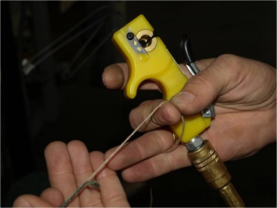
2. Take yarn and cut the two ends even while holding yarn on opposite side with index finger.
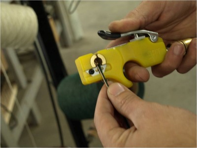
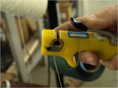
3. Be sure to cover hole completely while air valve is pressed.
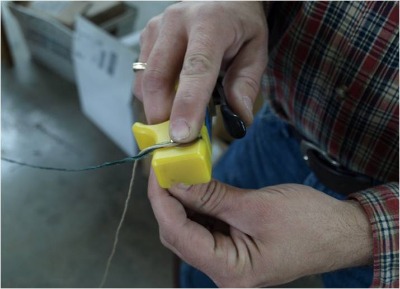
4. Press handle(time depends on yarn denier, but generally a second-long is more than enough)
5. You should end up with a small splice similar to the one shown.
We have many splicer chambers available for various yarn sizes because splice size is effected by chamber.
Note: Some yarn fibers require a slightly different technique which is slightly pulling yarn out from under finger while valve is pressed.
TDS-02 Thermal Beam Splicer
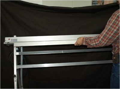
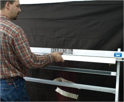
1. Remove Grip Bar.
2. Place in hangers.
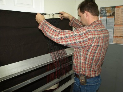
3. Load yarn from beam into slots.
4. Load yarn from header.
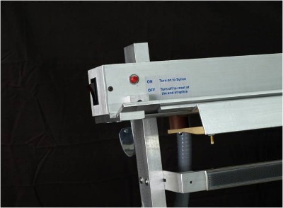
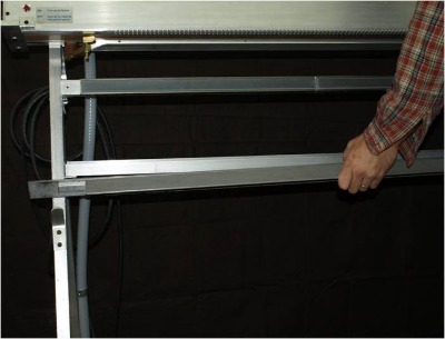
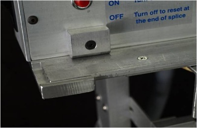
5. Be sure to secure all yarn on sticker bar below and that is snug.
6. Load grip bar at an angle.
7. Be sure grip bar is aligned and snaps into place.
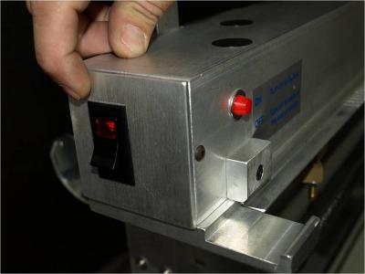
8. Turn switch on to splice.
9. Unit will automatically turn off at end of cycle(12-14 seconds). Indicator light will go out when cycle ends.
10. Remove grip bar and place in back in hangers.
PC-08 Creel System
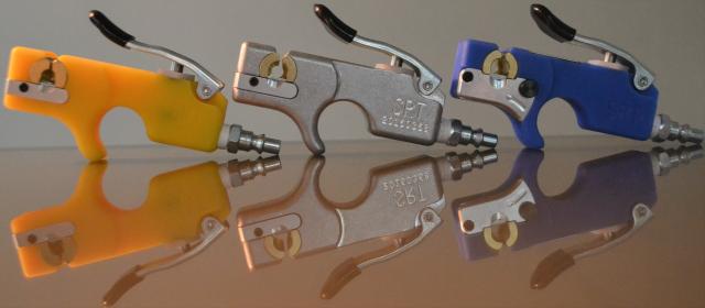
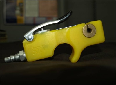
Here we hope to give you a better idea of how our new PC-08 creel systems work and how our other products relate to it. Below is a brief step-by-step illustration of the processes involved, complete with narration. This will be followed with some pictures and examples of our blow-back guns and 90° transition tube eyelets.
Before we go any farther, I will highlight some of the creel's main features, so that you may take them into consideration while viewing the pictures and details below. Note that these creels are custom-made and can be changed about to meet each individual company's specific needs. Also, our creels have indexable centers(as you'll soon see), in that, with a simple pivot of a lever, the centers of each yarn rack simultaneously go from a loading position to a operational position(and the reverse).
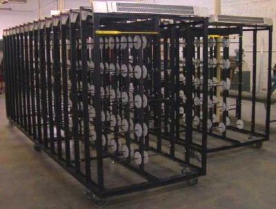
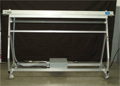
Here we have a basic overall front-view to help give you an idea of what we're looking at before going on to more in-depth pictures.
*Notice the wheel-locks, which guarantee these creels won't be going anywhere when in the lock position.
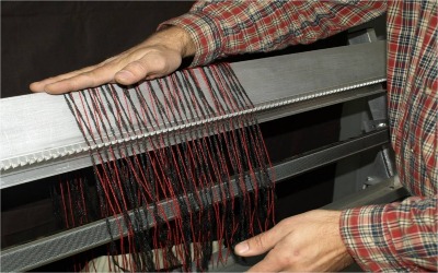
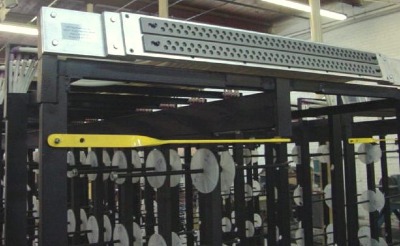
(Step 1) Zoomed view of the creel head with our slide guides and lever in action. These slide guides detach from the header and are used for loading yarn-ends into our model TDS-02 splicer much faster and easier than normal. This allows the operator to load up to 150 yarn ends into our model TDS-02 beam splicers for the splicing process. This is possible because these sliding guides can be easily detached from the creel and then loaded separately. The alternative being that you would normally have to manually load each yarn end, one at a time into an inclined creel head, thus making the process slow and pain-staking.
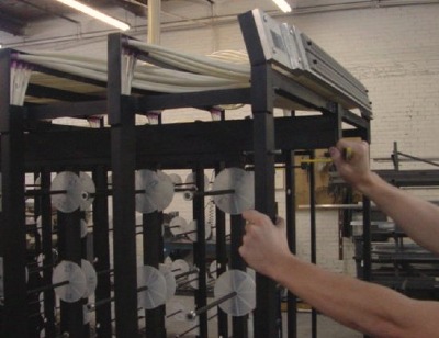
Also notice the loading (swivel) lever in yellow. When it's in the left position as shown in pic. 1, yarn loading is locked in place ready for operation. When it's brought to the right, it's in the loading position, allowing yarn to easily be loaded. You can see in pic. 2 just how easily this can be changed from one to another.
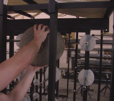
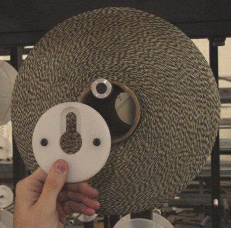
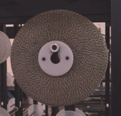
(Step 2) Here we illustrate loading the yarn and the final look before we lock everything back into place as shown previously(step 1) . Loading is quite easy. Place yarn on rack followed by our plastic package end-caps* as shown. No tools are required, end-caps simply slide and lock into place. These creels hold up to 12" diameter yarn packages and after this step, the yarn is ready to be spliced.
*End-caps are optional if needed and are used to compensate for damaged yarn tubes.
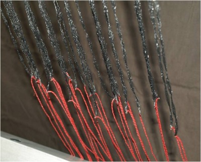
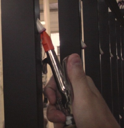
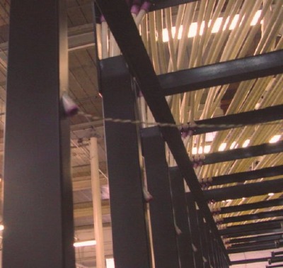
Here we illustrate how yarn is blown through the creel tubes, using easy-access port holes located in the runners. The 1st pic. also demonstrates a little of our blow-back guns in action. These are very effective tools(please see our blow-back gun page for more details) . Also note that the creel tubing runs inside vertical runner posts, preventing the tubes from being damaged while also offering a cleaner design.
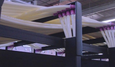
Finally, here is a picture to help show in further detail how clean and effective our tubing placement is, while giving you a complete idea of the yarn's traveling path. Also notice how our 90° transition tube eyelets(please see our eyelets page for more details) come into play. This helps reduce yarn drag and friction. This also helps eliminate yarn stretch and damage, resulting in a higher quality product.
These illustrations should give you a basic idea of how our creels work and their main features, leaving less to the imagination. If you are interested in having us build your company a custom creel package to your specifications, then please let us know. We supply only the highest quality products at the right price. Thank you for your time.